
UPDATE: Scroll down for Version 3, wireless remote!
So I had this idea…. remember when I combined Scratch with Sketchup to make ScratchUp? Well why not combine two of my favourite primary based microcontrollers to create a MiCrumBit???
This is the first of many ideas that I’ve got to combine the two different kits, some are dead simple and some are more complex.
I’d love to share the wiring and code with you for this so you can try it out for yourselves if you have both kits!
Firstly, the principles:
The Micro:bit already has buttons for inputs and is able to switch ‘on’ its terminals depending on which button is pushed. It also has the built in LED array, which for me made it the perfect ‘remote control’ as I knew I could make it display on the array which way the buggy was turning. However, it is a bit of a pain to run motors from and would require some extra bits of kit.
The Crumble and it’s handy powerful battery pack is able to power two motors and LEDs, but if you’ve got the school starter kits, only comes with one switch which is difficult to built a remote control with.
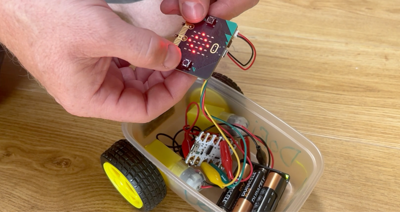
So using the best of both worlds; the Crumble as the power house and the Micro:bit as the controller, you can make a remote control buggy!
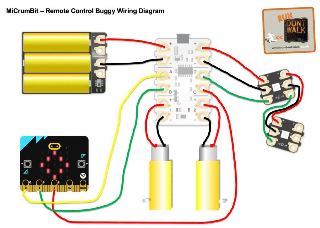
Here is the wiring: I used the standard configuration for the Crumble to connect to the motors and the LEDs, then connected the Crumble and Micro:bit terminals respectively: A – 0, B – 1, C – 2 with the Crumble D terminal obviously controlling the Crumble Sparkle LEDs.
Now, the way the Micro:bit interacts with the Crumble, is to set a current through the terminals (or pins) and for the Crumble to receive them. So here is my logic table/ Algorithm! I wanted the logo button to start the motors and stop them once they’d been started, with a second push…
| Mico:Bit terminal set to high | Micro:bit Array display | Crumble terminal set to receive | What happens to the motors | What happens to the LEDs |
| None | Diamond | Waiting to receive on A | All stop | Set to red |
| 0 (Set to Logo Button) | Forward Arrow | A | All go 100% | Set to blue |
| 1 (Set to button A) | Left Arrow | B | Left motor 100%, Right motor stop | Indicate left! |
| 2 (Set to button B) | Right Arrow | C | Right motor 100%, Left motor stop | Indicate right! |
| 0 (Set to Logo button) | Diamond | A | All Stop | Set to red |
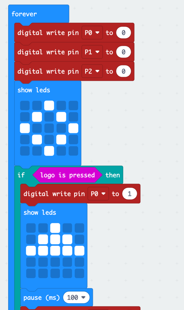
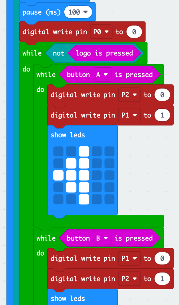
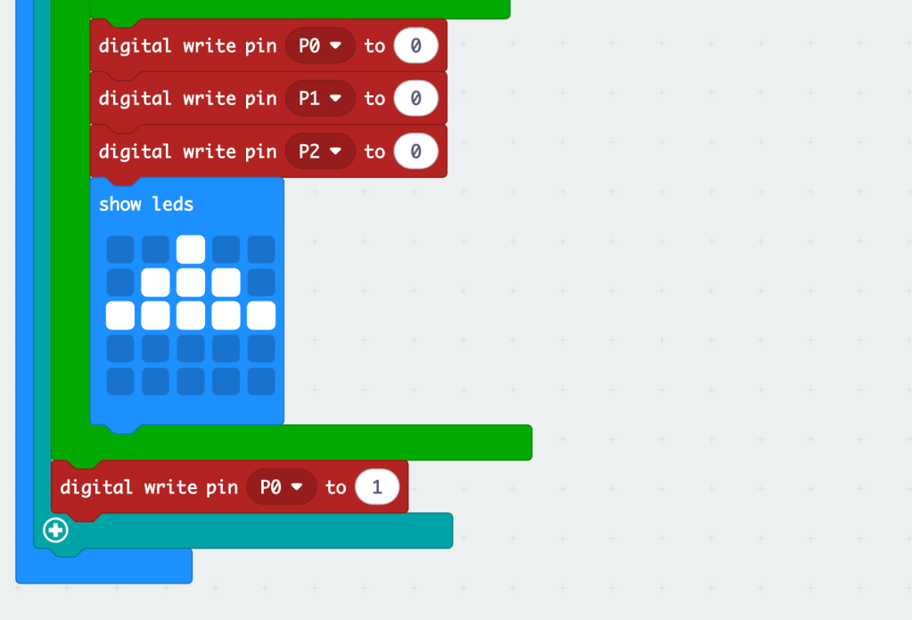
This is how I coded the Micro:bit. I wanted the LED array to show which way the buggy was turning, and to be able to hold A or B buttons down to turn, and also stop and start the motors with the logo button (The code was too long to do in one screenshot, so there are three shown, but you can hopefully see how they stitch together):
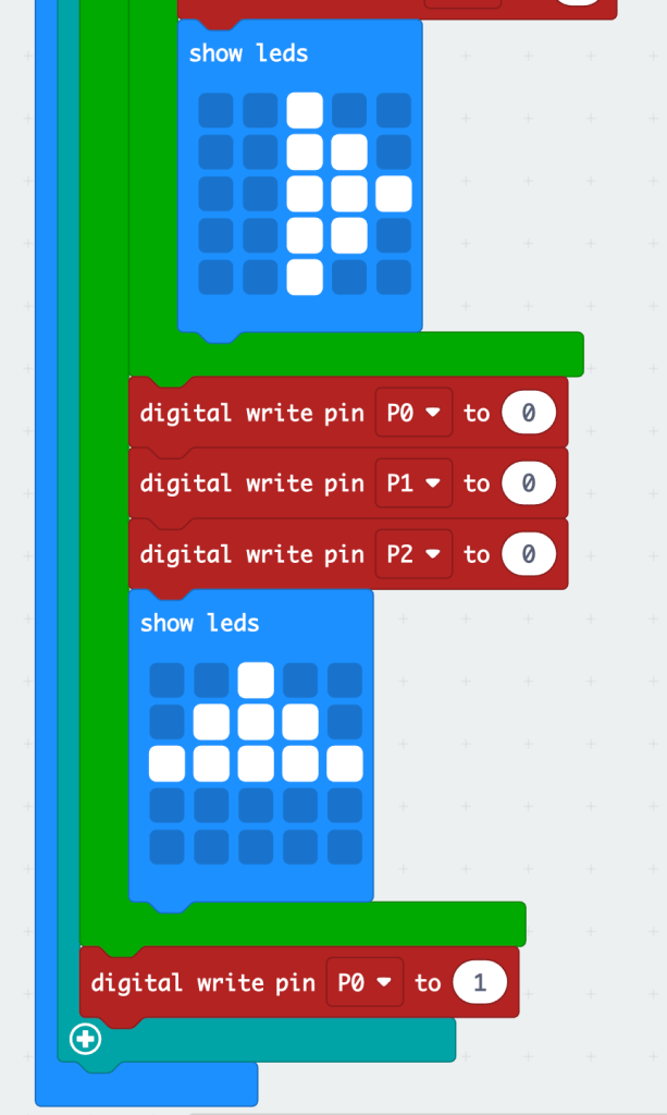
And here is the Crumble code:
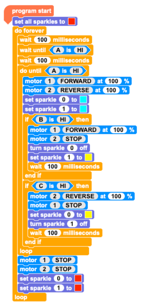
As you can see, I had to add millisecond pauses in, as for some reason the Micro:bit sends ‘pulses’ rather than a continuous current, so the motors would stutter a little or not stop completely.
But this seems to work a treat!
I had to do a fair bit of problem solving at first, and as you can see below, the use of variables to show what is actually going on was really helpful: if the Crumble is plugged in to your computer, it shows in real time what the variables are doing, so I could track which part of the program was running. When the variables were flicking between 0 and 1, it was obvious something wasn’t quite right. It turns out the pauses in the Crumble code made all the difference!!!

UPDATE: Version 3!
So I bought another Mico:bit so that I could use it as a transmitter to the original Micro:bit that controlled the Crumble, so that I could have a completely wireless remote. This would make an excellent project for children who are exploring topics such as the Mars Rover, or a lunar explorer, bomb disposal robots, or reserach robots on a volcano/ other place not suitable for humans. Also obviously Robot Wars too…
The code had to change a little bit to get this working, but here is the working model I ended up with!!
The Crumble code is exactly the same as above, but the two Micro:bit’s code are slightly differnt.
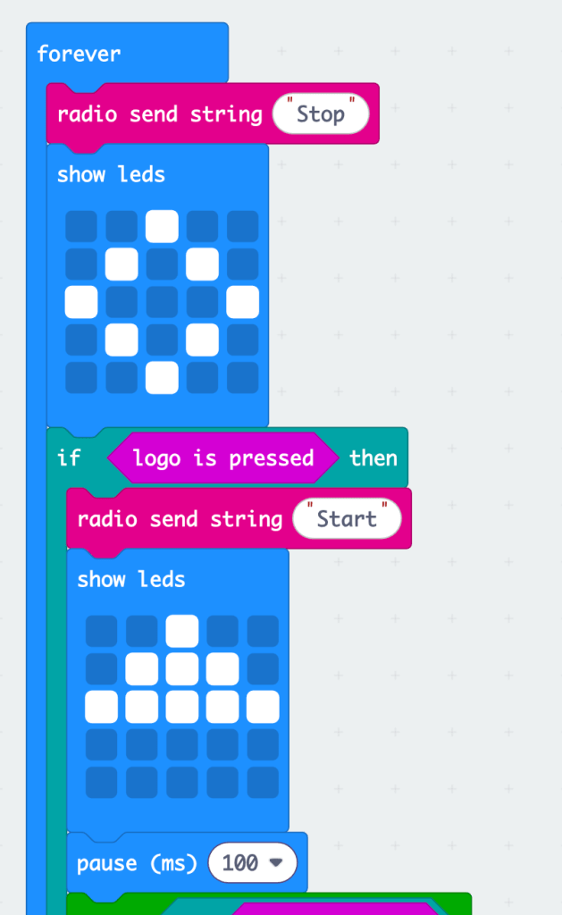
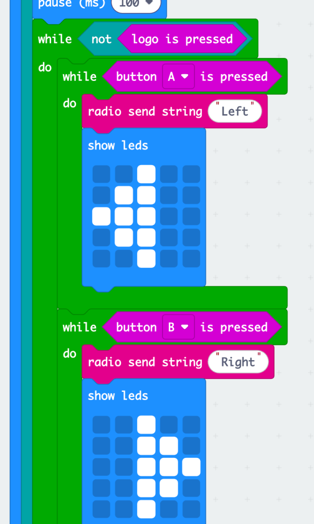
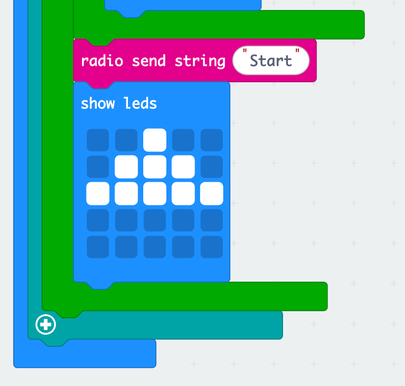
Here is the transmitter code, using variables for Start, Stop, Left and Right…
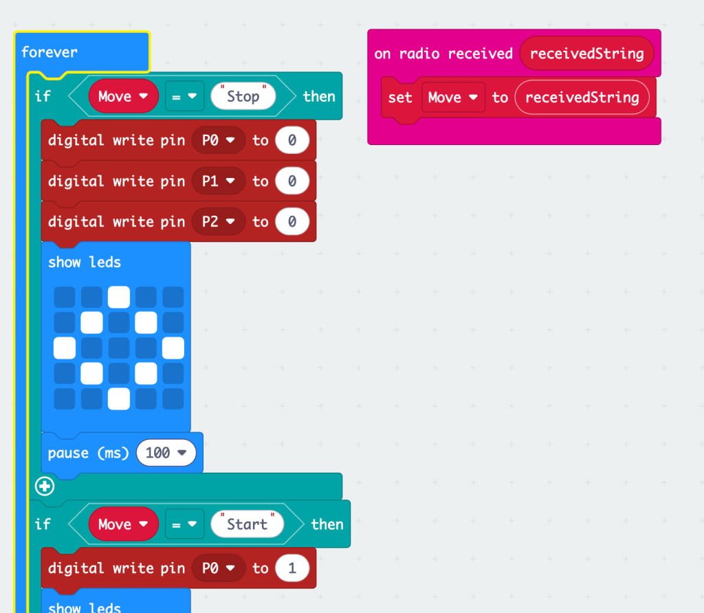
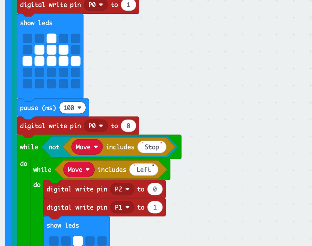
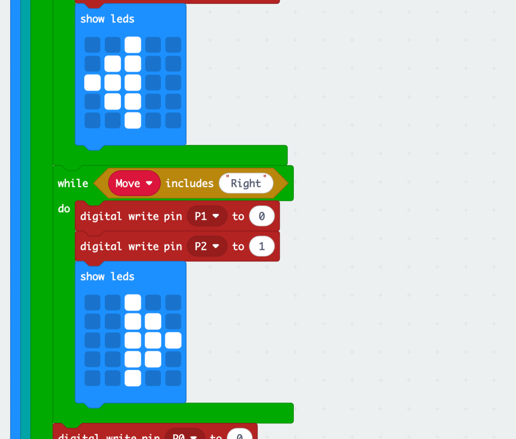
And here is the receiver Micro:bit code, that is wired into the buggy (I say permanently in the video, it’s not permanently, I’ve just wired it to the crumble and stuck it to the lid!)
Plenty more MiCrumBit projects coming soon, watch this space!!!
If you found this blog helpful, why not buy Phil a coffee!!

If you’re going to use this idea and would like to donate some money, please complete the form below. Thanks!
Make a one-time donation to show your appreciation:
Make a monthly donation
Make a yearly donation
Choose an amount
Or enter a custom amount
Your contribution is appreciated so much!
Your contribution is appreciated.
Your contribution is appreciated.
DonateDonate monthlyDonate yearly
Hi – Great work! I’ve bigged you up on my socials!
https://design-technology-tutor.com/
Let me know if you have any updates!
Best wishes,
Jeremy
LikeLike
That’s fantastic Jeremy, thanks! Do you have any interesting projects which combine DT and Computing that you’d like me to share on my blog?
LikeLike
Sorry no. I’m an online tutor and don’t get my hands dirty very often! I was about to run a joint project with IT but I left the school before we got it off the ground. Sounds great though!
LikeLike